MIL-PRF-29504/4D
Inches
mm
Inches
mm
.002
0.05
.127
3.23
.003
0.08
.130
3.30
.006
0.15
.225
5.72
.029
0.74
.295
7.49
.033
0.84
.305
7.75
.101
2.57
.853
21.67
.103
2.62
1.176
29.87
NOTES:
1. Dimensions are in inches, except diameter "A" which is dimensioned in metric microns only.
2. Metric equivalents are given for general information only.
3. Unless otherwise indicated, all diameters are to be concentric with respect to datum A within .003
inch (0.08 mm).
4. Dimensions apply after plating when applicable.
5. Ferrule end face may be flat or have a radius that does not exceed a curvature of 10 mm.
Recommended inspection documentation advises that an end face curvature of 25 mm falls
between that of a flat end face and one with a curvature of 10 mm.
6. Hole "A" diameter and tolerance are specified in table I.
7. Hole circular runout in table I relative to datum A.
8. Manufacturer's symbol or trademark location is in front of the first TICC band (see figure 1 of MIL-
PRF-29504). As an alternative to TICC bands, each digit of the TICC may be designated by the
number which corresponds to the color band. An alternate location of the marking shall be
allowed only in the case of insufficient surface area and only if approved by the qualifying activity.
9. Ferrule surface shown to have either a chamfer within 25o to 65o angle x .010 minimum or a
.010 R minimum.
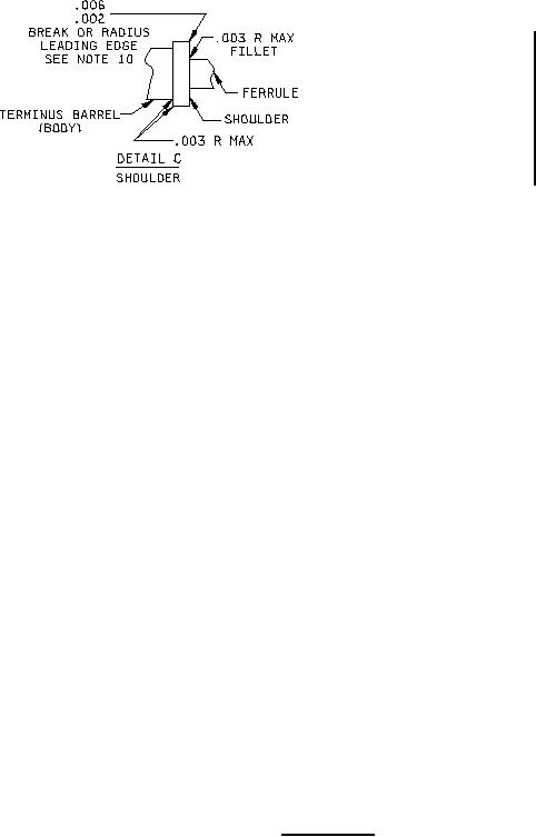
10. Optional dimension: Maximum allowable edge break is .015 inch (0.38 mm).
11. Termini qualified to this specification sheet shall meet the performance requirements when
inserted into a connector with clip-to-clip dimensions of .756 to .808 inch (19.20 to 20.52 mm).
12. Terminus design shall accommodate a single fiber cable with a maximum diameter of .087 inch
(2.2 mm).
13. Ferrule diameter for ceramic: .06246 to .06250 inches (1.5865 to 1.5875 mm), ferrule diameter
for metal: .06238 to .06248 inches (1.5824 to 1.5870 mm).
14. For interoperability with a standardized polishing puck, the length of exposed ferrule to the
terminus shoulder (end face to the front of the shoulder) shall be 0.262 inch (6.62 mm) minimum.
15. For style 1 and 3 terminus only, reduction of the .225 inch (5.72 mm) minimum length to .025 inch
(0.63 mm) is allowed. Additionally there shall be a smooth ramp transition on the terminus
between the terminus barrel and the crimp sleeve/heat shrink so as not to restrict the function of
the insertion and removal tool during the removal operation.
FIGURE 1. Pin terminus - Continued.
2
For Parts Inquires call Parts Hangar, Inc (727) 493-0744
© Copyright 2015 Integrated Publishing, Inc.
A Service Disabled Veteran Owned Small Business