MIL-PRF-24623C
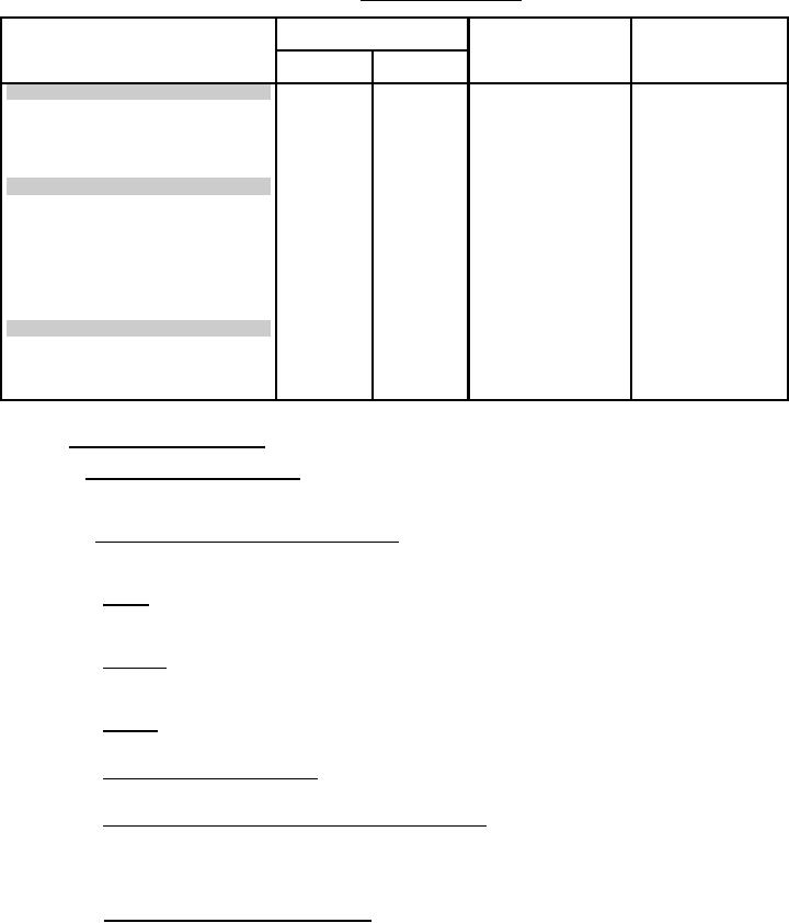
TABLE V.
Group C inspection.
Inspection
Application
Requirement
Test method
paragraph
paragraph
Cable
Fiber
splice
splice
Group I (all sample units)
Optical
X
X
3.6.1
4.7.3.1
Insertion loss
X
X
3.6.3
4.7.3.3
Return loss
X
3.6.5
4.7.3.5
Crosstalk
Group II (4 sample units)
X
3.5.13
4.7.2.13
Cable pull out
X
3.5.12
4.7.2.12
Fiber pull out
X
3.5.7
4.7.2.7
Axial compressive loading
X
3.5.6
4.7.2.6
Twist
X
X
3.5.9
4.7.2.9
Impact
X
3.5.8
4.7.2.8
Crush
X
X
3.5.11
4.7.2.11
Mechanical shock
Group III (4 sample units)
Temperature/humidity cycling
X
X
3.7.4
4.7.4.3
Temperature cycling
X
X
3.7.12
4.7.4.11
Life aging
X
X
3.7.2
4.7.4.1
Insertion loss
X
X
3.6.1
4.7.3.1
4.7
Methods of inspection.
4.7.1 Equivalent test methods. The use of equivalent test methods is allowed
provided the preparing activity and the qualifying activity have approved the use of
that equivalent test method by that manufacturer (see 6.3.4).
Visual and mechanical examination. The splice and splice parts shall be
4.7.2
examined to verify that materials, design, construction, physical dimensions, marking,
and workmanship are in accordance with the applicable requirements (see 3.3 and 3.4).
4.7.2.1 Size. Each dimension identified in the specification sheet (see 3.1) for
the splice parts shall be measured using calibrated measuring devices with the range,
precision and accuracy appropriate for the tolerances specified (see 3.5.1).
4.7.2.2 Weight. The splice or splice parts shall be weighed using calibrated scales
having the range, precision and accuracy appropriate for the tolerances specified (see
3.5.2).
4.7.2.3 Color. The color of the splice or splice parts shall be visually inspected
for compliance, as specified in the specification sheets (see 3.5.3).
4.7.2.4 Identification markings. Identification markings on the splice parts shall
be visually examined and measured for conformance with the requirements of 3.5.4.
4.7.2.5 Cable seal flexing (for cable splice only). The splice shall be tested in
accordance with TIA/EIA-455-1. After test exposure, the assemblies shall be visually
examined for seal damage. The cable splice assembly shall be exposed to 100 flexing
cycles, the assembly rotated approximately 90O in the flexing fixture and then exposed
to another 100 flexing cycles (see 3.5.5).
4.7.2.6 Twist (for cable splice only). The splice shall be tested in accordance
with TIA/EIA-455-36, for 50 cycles. The tensile load shall be 5 newtons and the
number of loads to be applied shall be one (see 3.5.6). The change in optical
12
For Parts Inquires call Parts Hangar, Inc (727) 493-0744
© Copyright 2015 Integrated Publishing, Inc.
A Service Disabled Veteran Owned Small Business