MIL-DTL-83522E
Inches
mm
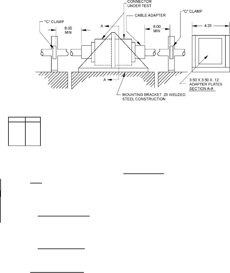
.12
3.1
.25
6.4
3.50
88.9
4.25
107.9
8.00
203.2
NOTES:
1. Dimensions are in inches.
2. Metric equivalents are given for general information only.
FIGURE 2. Vibration testing setup.
4.8.6 Shock. Optical discontinuities shall be measured during the test (see 4.7.9). The change in optical transmittance shall be
measured after the test (see 4.7.7). The connector shall be visually examined in accordance with 4.7.2 after the test. For temperature
range 1 testing, retightening of the connector after each blow is permitted. For temperature range 2 testing, initially mate the connector
assemblies and apply the specified torque value. Mark the position after the torque has been applied and check/record position after
each impact. For a mating connector containing a coupling ring ratchet mechanism, do not tighten the coupling ring after each impact if
the connector is being tested in addition to the terminus. Otherwise, retighten after each impact.
4.8.6.1 Temperature ranges 1 and 2. Connector mated pair shall be tested in accordance with MIL-S-901, grade A, class I.
Three blows (impacts) in each of three mutually perpendicular planes (axes) shall be performed (nine blows or impacts total), one plane
(axis) of which shall be parallel to the longitudinal axis of the connector. Standard shock fixture 4A for bulkhead mounting shall be
used. Measurement 3202 of MIL-STD-1678-3 shall be used to supplement setup and test procedure as appropriate for particular fiber
optic component configuration tested. Supplemental test fixture with mounting that is applicable shall be used as specified in
Measurement 3202 of MIL-STD-1678-3.
4.8.6.2 Temperature range 2 only. Connector mated pair shall be tested in accordance with TIA-455-14, test condition D.
Three shocks in each direction shall be applied along the three mutually perpendicular axes of the test sample (18 shocks).
Receptacles and panel or bulkhead mounted connectors and adapters shall be mounted by normal means. All other connectors and
adapters shall be rigidly clamped to the shock table.
4.8.7 Temperature/humidity cycling. Connector mated pairs shall be tested in accordance with method B of TIA-455-5 with
refinements specified in measurement 3302 of MIL-STD-1678-3 (such as the sub-cycle shall be included in the testing). The change in
21
For Parts Inquires call Parts Hangar, Inc (727) 493-0744
© Copyright 2015 Integrated Publishing, Inc.
A Service Disabled Veteran Owned Small Business