MIL-PRF-29504/5D
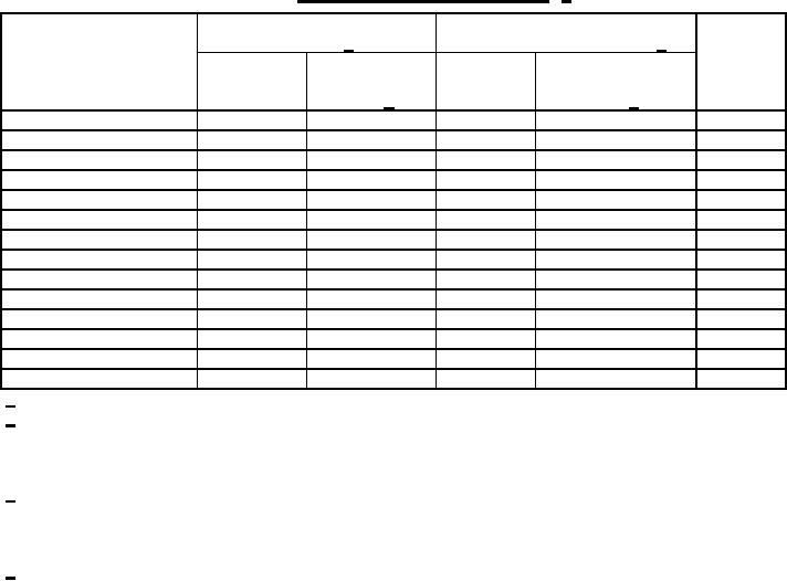
TABLE IV. Optical insertion loss performance. 1/
Termini in non-tight tolerance
Termini in tight tolerance
Fiber
M38999 2/
M38999/60 & M38999/61 3/
Ferrule
size
material
Initial
Insertion loss
Initial
Insertion
(um)
insertion
insertion
verification
loss verification
(dB) 4/
(dB) 4/
loss (dB)
loss (dB)
Single mode < 9/125
1.25
1.75
1.25
1.75
Ceramic
Single mode 9/125
0.75
1.25
0.75
1.25
Ceramic
50/125
1.50
2.00
1.00
1.50
Ceramic
62.5/125
1.00
1.50
0.75
1.25
Ceramic
62.5/125/polyimide
1.50
2.00
1.00
1.50
Ceramic
100/140
0.75
1.25
0.75
1.25
Ceramic
100/140/polyimide
1.50
2.00
1.00
1.50
Ceramic
> 100/140
1.50
2.00
1.25
1.75
Ceramic
50/125
1.50
2.00
1.25
1.75
Metal
62.5/125
1.25
1.75
1.00
1.50
Metal
62.5/125/polyimide
1.50
2.00
1.25
1.75
Metal
100/140
1.25
2.25
1.00
1.50
Metal
100/140/polyimide
1.50
2.50
1.00
1.75
Metal
200/230
1.50
2.50
1.00
1.75
Metal
1/ Optical loss performance based on use of specified fabrication procedure.
2/ Termini in a MIL-DTL-38999 connector that is other than MIL-DTL-38999 tight tolerance series III
connector (the latter being built to specification sheets MIL-DTL-38999/60 and MIL-DTL-38999/61
specific to fiber optic applications), the former distinguished from the tight tolerance type by denoting
as the MIL-DTL-38999 non-tight tolerance connector.
3/ Termini in a MIL-DTL-38999 tight tolerance series III connector (the MIL-DTL-38999/60 and MIL-DTL-
38999/61 specific to fiber optic applications) for shell sizes 9 through 19. For shell sizes 21 through
25, use performance requirements when termini are used in a MIL-DTL-38999 non-tight tolerance
connector.
4/ Insertion loss verification is an insertion loss performed after a series of environmental tests or
mechanical tests.
Mechanical. The following mechanical tests shall be performed in the sequence listed following the
post mating durability, return loss test: mechanical shock, vibration. For single mode termini, a
discontinuity is considered to be a reduction of optical transmittance of 0.5 dB or more for a duration of
50 microseconds or more (during vibration) or 100 milliseconds or more (during shock).
Mechanical shock. Mated connector assemblies shall be tested in accordance with the applicable
mechanical shock test listed below. Optical discontinuities shall be measured during the test. For
connectors of shell sizes 17 and greater, a minimum of four termini shall be monitored for
discontinuity. The change in optical transmittance shall be monitored after the test. The termini
shall be visually examined after the test to the extent feasible inside the connector. Termini shall not
be damaged and there shall be no loosening of parts. The requirement for optical discontinuity shall
be met during the test and the requirement for the change in optical transmittance shall be met after
the test. For testing, initially mate the connector assemblies and apply the specified torque value.
Mark the position after the torque has been applied and check/record position after each impact. For
a mating connector containing a coupling ring ratchet mechanism, do not tighten the coupling ring
after each impact if the connector is being tested in addition to the terminus. Otherwise, retighten
after each impact.
9
For Parts Inquires call Parts Hangar, Inc (727) 493-0744
© Copyright 2015 Integrated Publishing, Inc.
A Service Disabled Veteran Owned Small Business