MIL-PRF-28876/26D
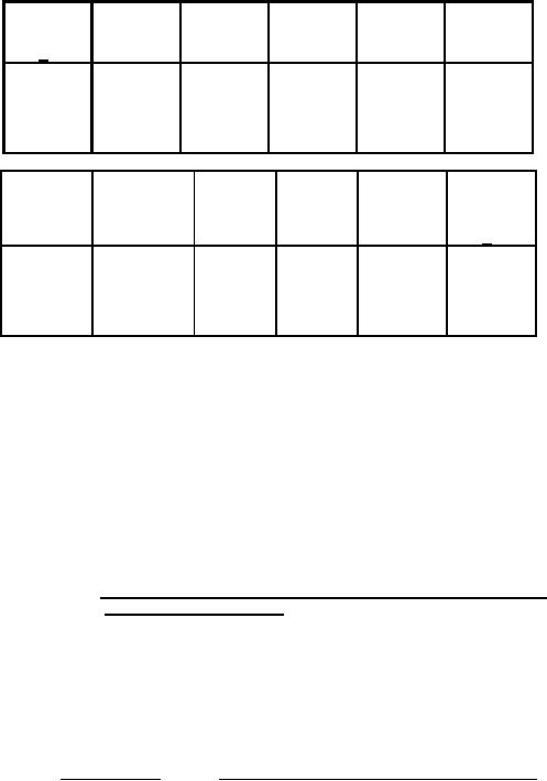
Shell
N
DD
Z
size
dia
W
X
dia
dia
6/
max
ref
max
15
1.263
.130
1.278
1.124
1.062
(32.08)
(3.30)
(32.46)
(28.55)
(26.97)
.115
1.238
(2.92)
(31.45)
NN
AH
AL
A
Y
Insert
across
max
flats
TIR
figure
flats
max
5/
1.153
4.613
3.60
.750
.968
B-3
(29.29)
(117.17)
(91.44)
(19.05)
(24.59)
or
B-4
1.144
4.573
(29.06)
(116.15)
NOTES:
1. Dimensions are in inches.
2. Metric equivalents are given for general information only.
3. Metric equivalents (mm) are in parentheses.
4. Dimensions apply to plated/finished part.
5. For insert arrangement, see the indicated figure in appendix B
of MIL-PRF-28876.
6. The color band shall be yellow and in accordance with EIA-359 for
all shell sizes.
7. For mating key dimensions and configurations, see MIL-PRF-28876,
figure A-3.
FIGURE 1.
Wall mounting receptacle connector with short
straight backshell - Continued.
REQUIREMENTS:
Dimensions and configurations: See figure 1 herein and MIL-PRF-28876,
appendix A, figure A-2, figure A-6, and figure A-7.
Weight (without termini):
Shell size
Weight (ounces (grams)), maximum
15
11.5 (326.025g)
Fiber optic cable:
Cable diameter: .315 ± .020 inch (8.00 ± 0.51 mm), or .425 ± .043 inch
(10.75 ± 1.07 mm).
Protective caps: Each connector shall be supplied with protective caps over
the front and rear portions of the connector.
Insert arrangement:
See appendix B of MIL-PRF-28876 for desired shell size.
2
For Parts Inquires call Parts Hangar, Inc (727) 493-0744
© Copyright 2015 Integrated Publishing, Inc.
A Service Disabled Veteran Owned Small Business